ROS2: Mapping and Navigation with Limo ROS2 ![]()
Limo is a smart educational robot published by AgileX Robotics. More details please visit: https://global.agilex.ai/
Four steering modes make LIMO substantially superior to other robots in its class. The available modes are: Omni-Wheel Steering, Tracked Steering, Four-Wheel Differential Steering and Ackermann Steering. These advanced steering modes plus a built-in 360° scanning LiDAR and RealSense infrared camera make the platform perfect for industrial and commercial tasks in any scenario. With these incredible features, LIMO can achieve precise self-localization, SLAM mapping, route planning and autonomous obstacle avoidance, reverse parking, traffic light recognition, and more.
Now we can experience Limo in ROS2!
Lidar Mapping
Cartographer
Introduction:
Cartographer is a set of SLAM algorithms based on image optimization launched by Google. The main goal of this algorithm is to achieve low computing resource consumption and achieve the purpose of real-time SLAM. The algorithm is mainly divided into two parts. The first part is called Local SLAM. This part establishes and maintains a series of Submaps through each frame of the Laser Scan, and the so-called submap is a series of Grid Maps. The second part called Global SLAM, is to perform closed-loop detection through Loop Closure to eliminate accumulated errors: when a submap is built, no new laser scans will be inserted into the submap. The algorithm will add the submap to the closed-loop detection.
How to operate:
Note: Before running the command, please make sure that the programs in other terminals have been terminated. The termination command is: Ctrl+c.
Note: The speed of limo should be slow in the process of mapping. If the speed is too fast, the effect of mapping will be affected.
First, start the LiDAR. Launch a new terminal and enter the command:
ros2 launch limo_bringup limo_start.launch.py
Then start the cartographer mapping algorithm. Open another new terminal and enter the command:
ros2 launch limo_bringup limo_cartographer.launch.py
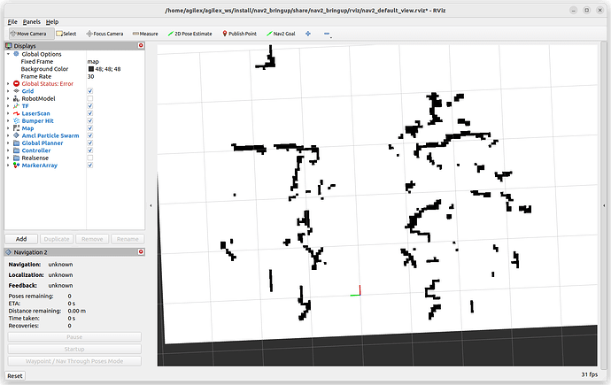
After launching successfully, the rviz visualization interface will be shown in the figure below:
After building the map, it is necessary to save it. Three following commands need to be entered in the terminal:
ros2 run nav2_map_server map_saver_cli -f map
Lidar navigation
use the map just built to navigate.
Navigation framework
The key to navigation is robot positioning and path planning. For these, ROS provides the following two packages.
(1)move_base:achieve the optimal path planning in robot navigation.
(2)amcl:achieve robot positioning in a two-dimensional map.
On the basis of the above two packages, ROS provides a complete navigation framework.
The robot only needs to publish the necessary sensor information and navigation goal position, and ROS can complete the navigation function. In this framework, the move_base package provides the main operation and interactive interface of navigation. In order to ensure the accuracy of the navigation path, the robot also needs to accurately locate its own position. This part of the function is implemented by the amcl package.
Move_base package
Move_base is a package for path planning in ROS, which is mainly composed of the following two planners.
(1) Global path planning (global_planner). Global path planning is to plan the overall path according to a given goal position and global map. In navigation, Dijkstra or A* algorithm is used for global path planning, and the optimal route from the robot to the goal position is calculated as the robot’s global path.
(2) Local real-time planning (local_planner). In practice, robots often cannot strictly follow the global path. So it is necessary to plan the path that the robot should travel in each cycle according to the map information and obstacles that may appear near the robot at any time. So that it conforms to the global optimal path as much as possible.
Amcl package
Autonomous positioning means that the robot can calculate its position on the map in any state. ROS provides developers with an adaptive (or kld sampling) Monte Carlo localization (amcl), which is a probabilistic positioning system that locates mobile robots in 2D. It implements an adaptive (or KLD-sampling) Monte Carlo localization, using particle filtering to track the pose of the robot on a known map.
Introduction of DWA_planner and TEB_planner
DWA_planner
The full name of DWA is Dynamic Window Approaches. The algorithm can search for multiple paths to avoid and travel, select the optimal path based on various evaluation criteria (whether it will hit an obstacle, the time required, etc.), and calculate the linear velocity and angular velocity during the driving cycle to avoid collisions with dynamic obstacles.
TEB_planner
The full name of “TEB” is Time Elastic Band Local Planner. This method performs subsequent modifications to the initial trajectory generated by the global path planner to optimize the robot’s motion trajectory. It falls under the category of local path planning. During the trajectory optimization process, the algorithm takes into account various optimization goals, which include but are not limited to minimizing overall path length, optimizing trajectory execution time, ensuring a safe distance from obstacles, passing through intermediate path points, and complying with the robot’s dynamics, kinematics, and geometric constraints. The “TEB method” explicitly considers the dynamic constraints of time and space during the robot’s motion. For instance, it considers limitations on the robot’s velocity and acceleration.
Limo navigation
Note: In the four-wheel differential mode, the omnidirectional wheel mode and the track mode, the file run for the navigation is the same.
Note: Before running the command, please make sure that the programs in other terminals have been terminated. The termination command is: Ctrl+c.
(1)First launch the LiDAR and enter the command in the terminal::
ros2 launch limo_bringup limo_start.launch.py
(2)Launch the navigation and enter the command in the terminal:
ros2 launch limo_bringup limo_nav2.launch.py
Note: If it is Ackermann motion mode, please run:
ros2 launch limo_bringup limo_navigation_ackerman.launch
After launching successfully, the rviz interface will be shown in the figure below:
Note: If you need to customize the opened map, please open the limo_navigation_diff.launch file to modify the parameters. The file directory is: ~/agilex_ws/src/limo_ros/limo_bringup/launch. Please modify map02 to the name of the map that needs to be replaced.
(3) After launching the navigation, it may be observed that the laser-scanned shape does not align with the map, requiring manual correction. To rectify this, adjust the actual position of the chassis in the scene displayed on the rviz map.
Use the rviz tools to designate an approximate position for the vehicle, providing it with a preliminary estimation. Subsequently, use the handle tool to remotely rotate the vehicle until automatic alignment is achieved. Once the laser shape overlaps with the scene shape on the map, the correction process is concluded. The operational steps are outlined as follows:
The correction is completed:
(4) Set the navigation goal point through 2D Nav Goal.
A purple path will be generated on the map. Switch the handle to command mode, and Limo will automatically navigate to the goal point.
(5) Multi-point navigation
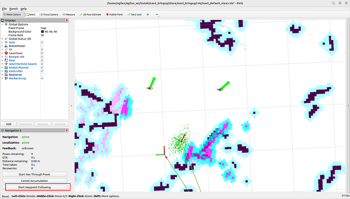
Click the button in the red box to enter multi-point navigation mode.
Click Nav2 Goal and add points on the map. After adding points, click the button in the red box to start navigation
#Visual mapping
Introduction and use of ORBBEC®Dabai
ORBBEC®Dabai is a depth camera based on binocular structured light 3D imaging technology. It mainly includes a left infrared camera (IR camera1), a right infrared camera (IR camera2), an IR projector, and a depth processor. The IR projector is used to project the structured light pattern (speckle pattern) to the goal scene, the left infrared camera and the right infrared camera respectively collect the left infrared structured light image and the right infrared structured light image of the goal, and the depth processor executes the depth calculation algorithm and outputs the depth image of the goal scene after receiving the left infrared structured light image and the right infrared structured light image.
| Parameter name | Parameter index |
|---|---|
| The distance between the imaging centers of the left and right infrared cameras | 40mm |
| Depth distance | 0.3-3m |
| Power consumption | The average power consumption of the whole machine <2W; The peak value at the moment the laser is turned on <5W (duration: 3ms); Typical standby power consumption <0.7W. |
| Depth map resolution | 640X400@30FPS 320X200@30FPS |
| Color map resolution | 1920X1080@30FPS 1280X720@30FPS 640X480@30FPS |
| Accuracy | 6mm@1m (81% FOV area participates in accuracy calculation*) |
| Depth FOV | H 67.9° V 45.3° |
| Color FOV | H 71° V43.7° @1920X1080 |
| Delay | 30-45ms |
| Data transmission | USB2.0 or above |
| Supported operating system | Android / Linux / Windows7/10 |
| Power supply mode | USB |
| Operating temperature | 10°C ~ 40°C |
| Applicable scene | Indoor / outdoor (specifically subject to application scenes and related algorithm requirements) |
| Dustproof and waterproof | Basic dustproof |
| Safety | Class1 laser |
| Dimensions (mm) | Length 59.6 X width 17.4 X thickness 11.1mm |
After knowing the basic parameters of ORBBEC®Dabai, start to practice:
Note: Before running the command, please make sure that the programs in other terminals have been terminated. The termination command is: Ctrl+c
First ,start the ORBBEC®Dabai camera. Run the following command:
ros2 launch astra_camera dabai.launch.py
Open rqt_image_view:
ros2 run rqt_image_view rqt_image_view
Introduction of rtabmap algorithm
RTAB-Map (Real-Time Appearance-Based Mapping) is an algorithm for Simultaneous Localization and Mapping (SLAM) that aims to achieve a balance between real-time performance and map quality. RTAB-Map is a graph-based SLAM system that can build dense 3D maps at runtime (real-time).
Some of the key features and components of RTAB-Map are as follows:
- Real-time Performance: RTAB-Map is specifically designed to operate in real-time applications, such as robot navigation and augmented reality systems. It employs an algorithm that minimizes computational requirements while achieving fast and accurate map construction and positioning, even with limited computing resources.
- Feature-based SLAM: RTAB-Map utilizes visual and inertial sensor data to perform feature matching. It extracts key points and descriptors from consecutive frames to enable simultaneous localization and mapping (SLAM), even without precise motion models. This feature allows for robust mapping and localization in dynamic environments.
- Environment Awareness: RTAB-Map incorporates environment awareness techniques to enhance map quality. It takes into account depth information, parallax, and other environmental factors, which is particularly beneficial in scenarios with less texture or repetitive structures. This improves the reliability and accuracy of the generated maps.
- Loop Detection and Closed-loop Optimization: RTAB-Map includes loop detection mechanisms to identify previously visited areas within the map. It then employs optimization techniques to correct previous trajectories and maps based on the loop closure information. This ensures consistency in the map representation and reduces errors over time.
- RGB-D Sensor Support: RTAB-Map provides direct support for RGB-D sensors, such as the Microsoft Kinect. By utilizing depth information from these sensors, RTAB-Map enhances the accuracy and density of the generated maps. This support for RGB-D sensors enables more detailed and comprehensive mapping capabilities.
How to achieve Rtabmap algorithm with Limo ROS2
Note: Before running the command, please make sure that the programs in other terminals have been terminated. The termination command is: Ctrl+c.
Note: The speed of limo should be low in the process of mapping. If it is too fast, the effect of mapping will be affected.
(1)First launch the LiDAR. Enter the command in the terminal:
ros2 launch limo_bringup limo_start.launch.py
(2)Launch the camera. Enter the command in the terminal:
ros2 launch astra_camera dabai.launch.py
(3)Launch the mapping mode of the rtabmap algorithm. Enter the command in the terminal:
ros2 launch limo_bringup limo_rtab_rgbd.launch.py
After building the map, the program can be terminated directly. The built map will be automatically saved in the main directory as a .ros file named rtabmap.db. The .ros folder is hidden and can be displayed using the Ctrl+h command.
Rtabmap algorithm navigation
Note: Before running the command, please make sure that the programs in other terminals have been terminated. The termination command is: Ctrl+c.
(1)First launch the LiDAR. Enter the command in the terminal:
ros2 launch limo_bringup limo_start.launch.py
(2)Launch the camera. Enter the command in the terminal:
ros2 launch astra_camera dabai.launch.py
(3)Start the mapping mode of rtabmap algorithm. Enter the command in the terminal:
ros2 launch limo_bringup limo_rtab_rgbd.launch.py localization:=true
(4)Start the navigation algorithm. Enter the command in the terminal:
ros2 launch limo_bringup limo_rtab_nav2.launch.py
Visual navigation
Rtabmap algorithm navigation
Note: Before running the command, please make sure that the programs in other terminals have been terminated. The termination command is: Ctrl+c.
(1)First launch the LiDAR. Enter the command in the terminal:
ros2 launch limo_bringup limo_start.launch.py
(2)Launch the camera. Enter the command in the terminal:
ros2 launch astra_camera dabai.launch.py
(3)Start the mapping mode of rtabmap algorithm. Enter the command in the terminal:
ros2 launch limo_bringup limo_rtab_rgbd.launch.py localization:=true
(4)Start the navigation algorithm. Enter the command in the terminal:
ros2 launch limo_bringup limo_rtab_nav2.launch.py
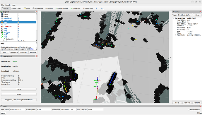
(5)Because visual positioning is used, there is no need for calibration when using rtabmap navigation. Users can directly start setting the target points and proceed with navigation. The operational steps are shown in the figure.
A green path will be generated in the map. Switch the handle to command mode, and Limo will automatically navigate to the goal point.


